Three-position disconnector
Direct-drive SAX-12/T with uniform electric field distribution and high dynamic and thermal stability. Its dual-aperture mechanism incorporates mechanical and electrical interlocks.
Compact, maintenance-free cubicle-type switchgear for control, protection, and monitoring in primary distribution systems.
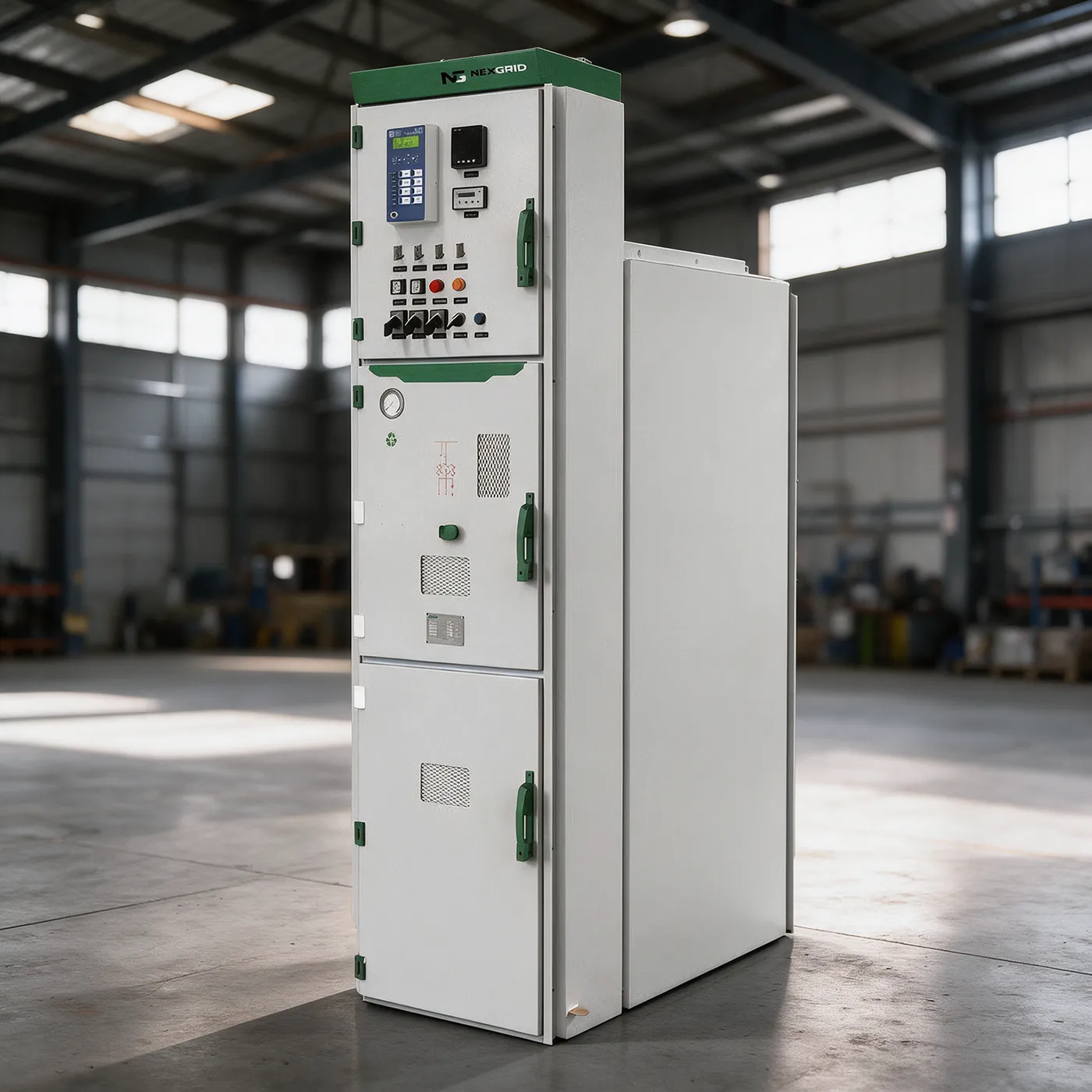 N₂ Cubicle Type Gas Insulated Switchgear
MAX-12 uses nitrogen at slightly positive pressure as its insulating medium, with a vacuum circuit breaker and three-position disconnector inside a sealed compartment.
The gas chamber is welded from 3 mm stainless steel. Its compact, long-life design reduces space requirements and protects primary components from environmental conditions.
For 12 kV three-phase systems with a single busbar or sectionalized single busbar: power generation, industrial and mining distribution, substations, and starting large high-voltage motors.
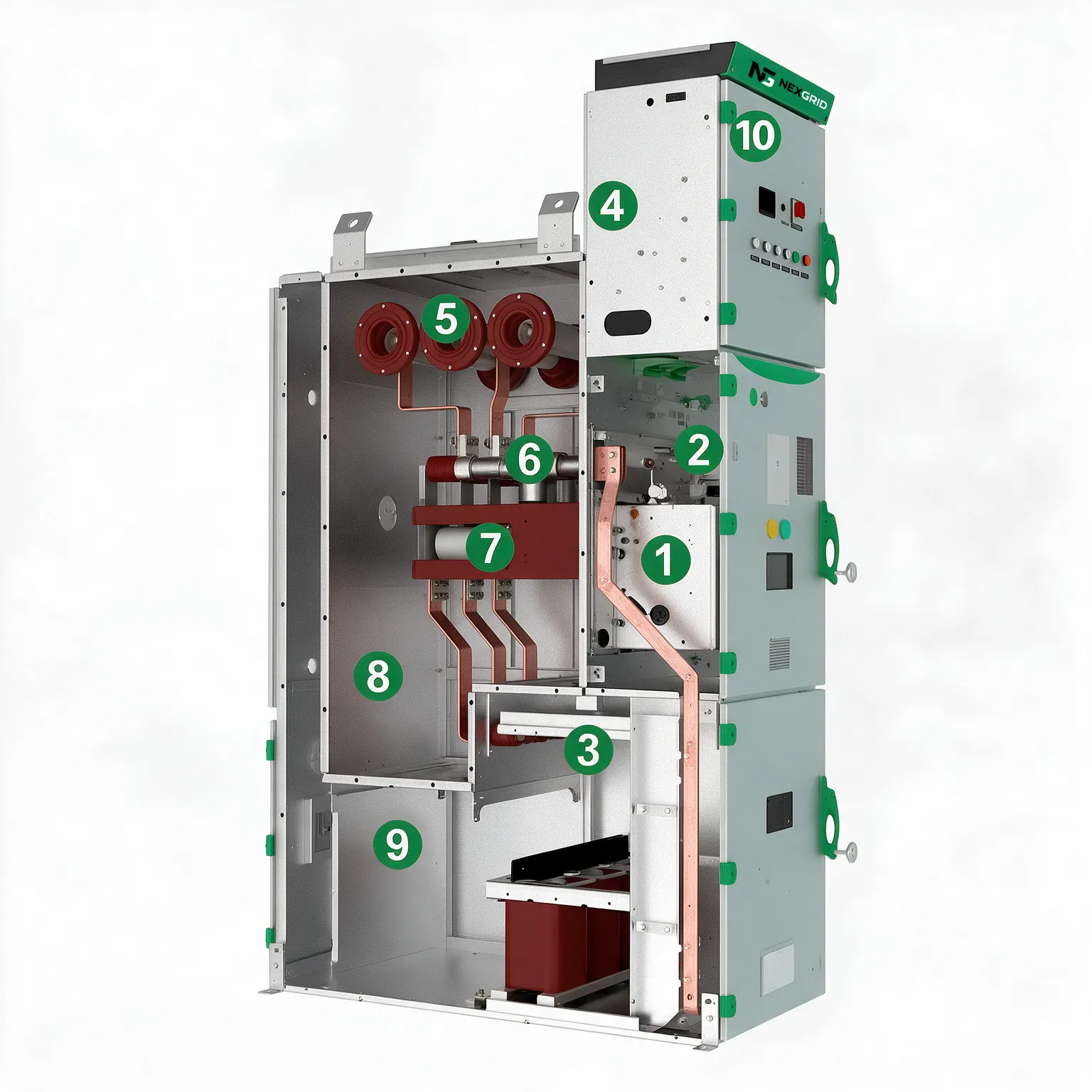
Main assemblies are integrated into modules designed to simplify control and enhance reliability.
Direct-drive SAX-12/T with uniform electric field distribution and high dynamic and thermal stability. Its dual-aperture mechanism incorporates mechanical and electrical interlocks.
Modular VAX-12/T assembly with optimized transmission and reliable interlocks for circuit switching.
Reduces the number of secondary components and improves overall control system reliability.
Values from the MAX-12 Series v2 brochure's technical table. Final selection depends on the project configuration.
| Parameter | Value |
|---|---|
| Rated voltage | 12 kV |
| Rated frequency | 60 Hz |
| Rated continuous current | 1,250 / 2,500 / 3,150 A |
| Power-frequency withstand voltage, 1 min | 42 kV phase-to-phase and phase-to-ground · 48 kV across the isolating distance · 2 kV in auxiliary and control circuits |
| Lightning impulse withstand voltage | 75 kV phase-to-phase and phase-to-ground · 85 kV across the isolating distance |
| Rated short-time withstand current | 25 / 31.5 / 40 kA, 4 s |
| Rated peak withstand current | 63 / 80 / 100 kA |
| Short-circuit breaking current | 25 / 31.5 / 40 kA |
| Short-circuit making current | 63 / 80 / 100 kA |
| Circuit breaker electrical endurance | 30 operations |
| Rated operating sequence | O–0.3 s–CO–180 s–CO |
| Circuit resistance | ≤ 120 μΩ (1,250 A) · ≤ 80 μΩ (2,500 / 3,150 A) |
| Circuit breaker mechanical endurance | 20,000 operations |
| Disconnector / grounding switch | 5,000 operations |
| Rated filling pressure at 20 °C | 0.02 MPa |
| Annual leakage rate | ≤ 0.01% |
| Insulating gas | N₂ |
| Compartment protection | IP2X |
| Gas tank protection | IP67 |
| Enclosure protection | IP41 · IK10 |
| Internal arc classification | AFLR 31.5 kA / 1 s · 40 kA / 0.5 s |
Frequency: the technical table specifies 60 Hz, while the brochure overview mentions 50 Hz. Confirm the required frequency with Nexgrid.
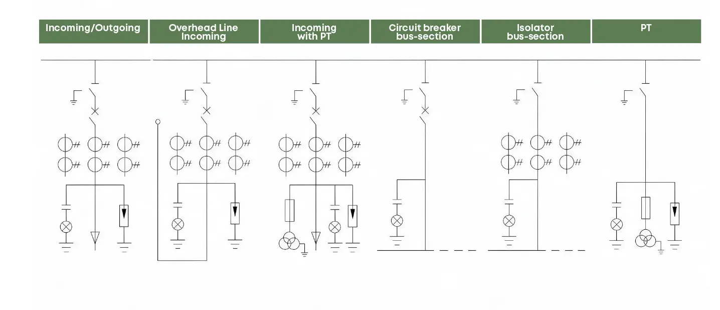
The platform offers basic configurations for incoming and outgoing feeders, metering, bus ties, and sectionalizing.
IEC 62271-100:2012 · alternating-current circuit breakers.
IEC 62271-105 · switch-fuse combinations.
IEC 62271-102 · disconnectors and grounding switches.
IEC 62271-103 · switches above 1 kV and up to 52 kV.
IEC 62271-200:2011 · metal-enclosed switchgear.
IEC 62271-1:2007 · common specifications.
Share your diagram, rated current, short-circuit level, and required functions to define your MAX-12 configuration.