Fully sealed system
Primary components remain inside an IP67 tank, protected from moisture, dust, and environmental conditions.
Compact, modular, fully sealed ring main unit for switching, control, and protection in secondary distribution networks.
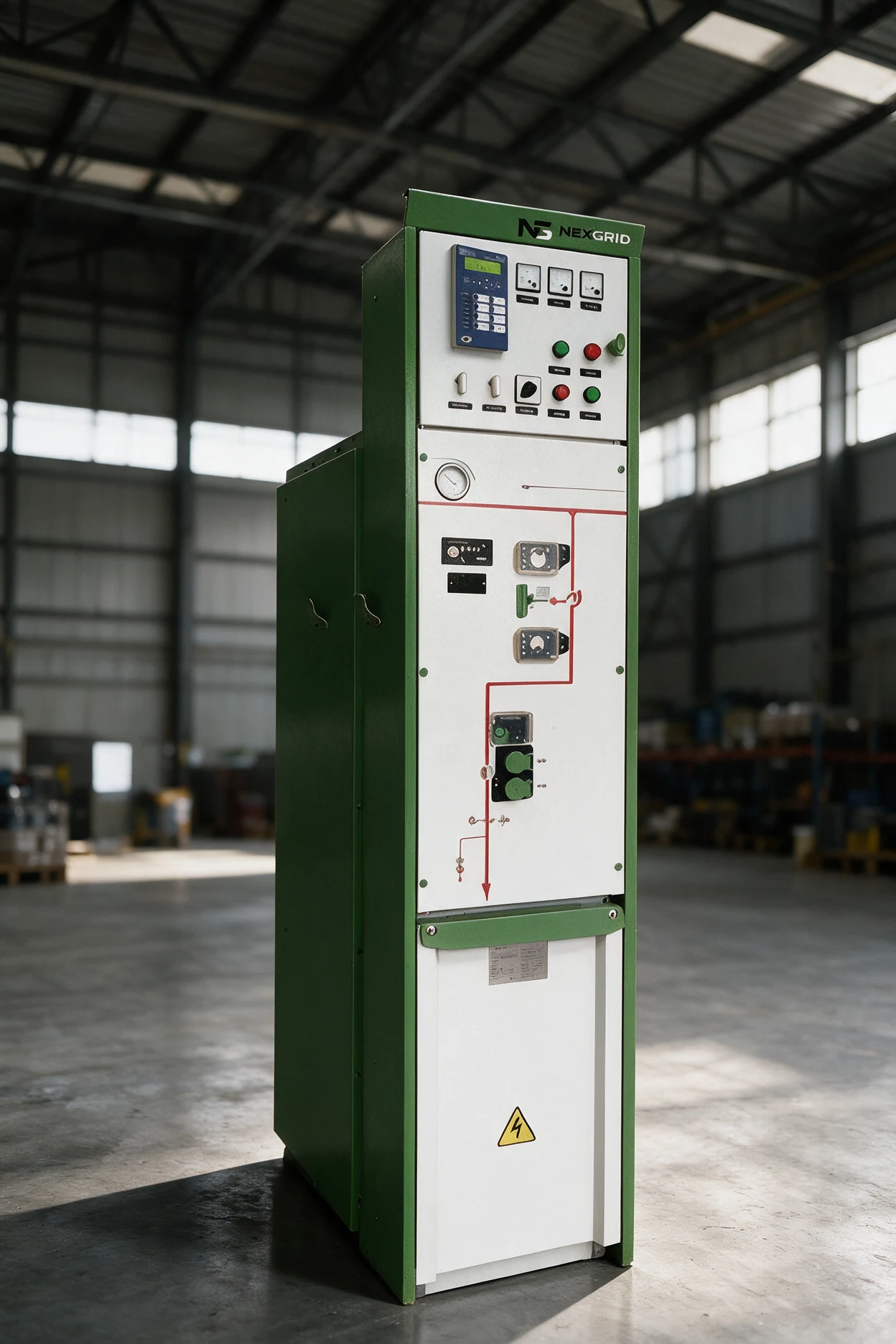 Eco-friendly Gas Insulated RMU
MGA-12 is a nitrogen-insulated ring main unit developed to reduce environmental impact without compromising safety or continuity.
All primary components and switching elements are housed in a sealed stainless steel tank. Its modular architecture combines compact and extensible units for different secondary substation arrangements.
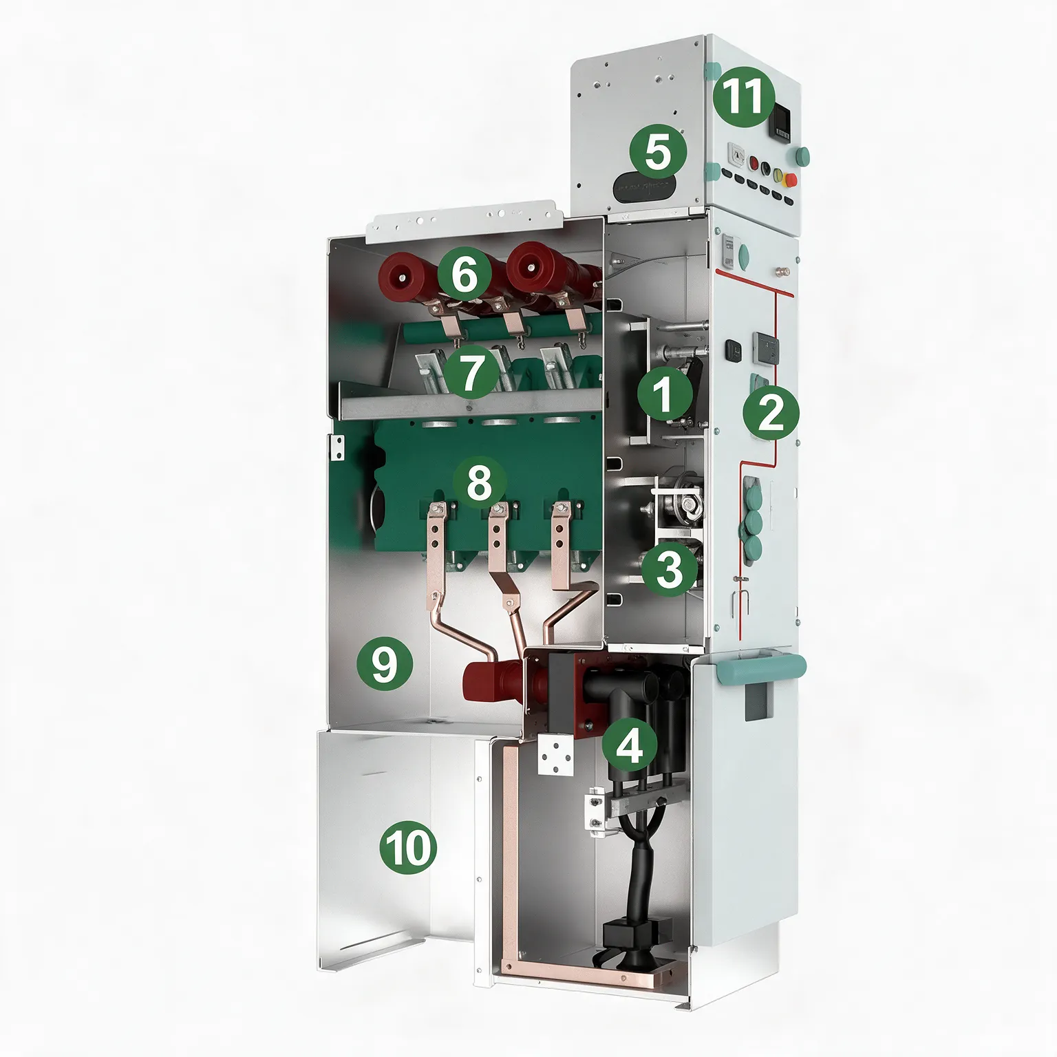
Primary components remain inside an IP67 tank, protected from moisture, dust, and environmental conditions.
The disconnector uses a spring and dual operating apertures, with a rigid interlock to the circuit breaker mechanism to reduce the risk of incorrect operation.
Cam transmission and vacuum interrupter mounting keep overtravel and contact gap stable. The mechanism incorporates a rapid reclosing function.
The integrated modular control unit is located at the front for easy inspection and service. According to the brochure, the insulation design limits partial discharge to less than 20 pC at 1.1 times rated voltage.
Basic units can form common-enclosure arrangements with up to four functions.

Feeder switching with a rated current of 630 A.
Circuit protection at 630 / 1,250 A and breaking capacities of 20 / 31.5 kA. Configurations with an upper or lower disconnector.
125 A switch-fuse combination, subject to the selected high-voltage fuse.
Direct connection unit for integration into the distribution architecture.
Unit for potential transformers and metering functions.
Values from the MGA-12 Series v2 brochure's technical table. Final selection depends on the project configuration.
Scroll the table to compare all three modules.
| Parameter | C · Load-break switch | F · Switch-fuse combination | V · Vacuum circuit breaker |
|---|---|---|---|
| Rated voltage | 12 kV | 12 kV | 12 kV |
| Rated frequency | 60 Hz | 60 Hz | 60 Hz |
| Rated current | 630 A | 125 A¹ | 630 / 1,250 A |
| Power-frequency withstand voltage, 1 min: phase-to-phase and phase-to-ground | 42 kV | 42 kV | 42 kV |
| Power-frequency withstand voltage, 1 min: isolating distance | 48 kV | 48 kV | 48 kV |
| Auxiliary and control circuit withstand voltage | 2 kV | 2 kV | 2 kV |
| Lightning impulse withstand voltage: phase-to-phase and phase-to-ground | 75 kV | 75 kV | 75 kV |
| Lightning impulse withstand voltage: isolating distance | 85 kV | 85 kV | 85 kV |
| Rated short-time withstand current | 20 kA / 4 s | — | 20 / 31.5 kA, 4 s |
| Rated peak withstand current | 50 kA | — | 50 / 80 kA |
| Short-circuit breaking current | — | Limited by the fuse² | 20 / 31.5 kA |
| Short-circuit making current | 50 / 63 kA | Limited by the fuse² | 50 / 80 kA |
| Load-breaking current | 630 A | — | — |
| Closed-loop breaking current | 630 A | — | — |
| Rated operating sequence | — | — | O–0.3 s–CO–180 s–CO |
| Circuit breaker mechanical endurance | 10,000 operations | 10,000 operations | 10,000 operations |
| Disconnector / grounding switch endurance | 3,000 operations | 3,000 operations | 3,000 operations |
| Circuit resistance | ≤ 150 μΩ | ≤ 400 μΩ | ≤ 150 μΩ |
| Relative gas pressure at 20 °C | 0.02 MPa | 0.02 MPa | 0.02 MPa |
| Annual leakage rate³ | ≤ 0.01 | ≤ 0.01 | ≤ 0.01 |
| Insulating gas | N₂ | N₂ | N₂ |
| Compartment protection | IP2XC | IP2XC | IP2XC |
| Tank protection | IP67 | IP67 | IP67 |
| Enclosure protection | IP41 · IK10 | IP41 · IK10 | IP41 · IK10 |
| Internal arc classification | AFLR 25 kA / 1 s | AFLR 25 kA / 1 s | AFLR 25 kA / 1 s |
¹ Current determined by the fuse rating. ² Performance limited by the high-voltage fuse. ³ The brochure states ≤ 0.01 and labels the unit as “Year” without clarifying whether it is a percentage; confirm this value with Nexgrid.
Basic modules can be combined in a shared enclosure to meet specific switching, protection, connection, and metering needs.
| Type | Extension | Width (W) | Height (H) | Depth (D) |
|---|---|---|---|---|
| C | Top | 420 mm | 1,950 mm | 850 mm |
| Side | 420 mm | 2,000 mm | ||
| V | Top | 420 mm | 1,950 mm | 850 mm |
| Side | 420 mm | 2,000 mm | ||
| PT | Top | 600 mm | 1,950 mm | 850 mm |
| Side | 600 mm | 2,000 mm | ||
| D | Top | 420 mm | 1,950 mm | 850 mm |
| Side | 420 mm | 2,000 mm |
IEC 62271-100:2012 · alternating-current circuit breakers.
IEC 62271-105 · switch-fuse combinations.
IEC 62271-102 · disconnectors and grounding switches.
IEC 62271-103 · switches above 1 kV and up to 52 kV.
IEC 62271-200:2011 · metal-enclosed switchgear.
IEC 62271-1:2007 · common specifications.
Share your diagram, current, switching functions, and protection strategy to define your MGA-12 configuration.